
When switching on a DC solenoid valve, current and voltage curves are key parameters for assessing the behavior of the solenoid coil. In many applications, the coil is simplified as an idealized L-R series circuit—a combination of a fixed inductance (L) and an ohmic resistance (R) that describes the copper losses of the coil wire.
But what does this look like in reality? Let's take a closer look at the actual switching process.
1. The idealized view: The L-R series circuit
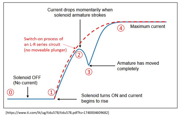
In a simple model (L-R circuit), the current curve when switching on is as follows:
- The current rises exponentially until it is limited by the series resistance.
- This curve is reproducible and predictable – but only under the assumption that the inductance remains constant.
In practice, however, this is not the case, as one crucial factor changes dynamically: the magnetic core.
2. The real dynamics of the magnetic coil
The solenoid coil of a valve contains a movable magnetic core that undergoes a defined movement during the switching process. This movement significantly influences the inductance of the coil and leads to a more complex current curve.
The actual process can be divided into five steps:
Step 0 – Retirement
- The solenoid valve is switched off.
- No current is flowing through the coil.
Step 1 – Switch on
- The magnetic coil is supplied with voltage.
- The current begins to rise in line with the idealized model.
Step 2 – Start of movement
- At a certain point, the magnetic core begins to move.
- This movement changes the magnetic properties of the system: the inductance increases.
- Due to the induced counter-EMF (electromagnetic force), the current drops briefly despite the constant voltage.
Step 3 – End position reached
- The magnetic core has reached its end position.
- The movement ends, the inductance remains constant.
- The current begins to rise again – this time similar to the idealized curve.
Step 4 – Maximum current
- The current reaches its maximum.
- This value is limited by the ohmic resistance of the coil.
Conclusion
The switching process of a DC solenoid valve is more complex than a simple L-R model suggests. The movement of the magnetic core has a significant impact on the current flow:
- Dynamic inductance due to movement of the core
- Temporary current drop due to counter-EMF
- Current increase after movement ends until stable final value is reached
A deeper understanding of these processes is essential for the precise design and optimization of solenoid valve systems – especially for special solutions and demanding applications.